Create a grid or fenestrated surface in OpenSCAD
OpenSCAD is a popular tool for designing 3D models using a scripting interface. Different to programs that let you shape a model directly, this approach lets you specify measurements precisely and reproduce designs easily.
Setting things up
Define three variables for the surface size:
x = 100;
y = 100;
z = 1;
Defining the windows
Define the number of holes on each axis and their relative size:
fen_x = 15; // fenestrations on x axis
fen_y = 15; // fenestrations on y axis
fen_size = 5; // size of fenestrations as a % of total axis size
Calculating sizes
Using the variables defined above, calculate the window size and spacing:
// calculate fenestration size
fen_size_x = fen_size * x / 100;
fen_size_y = fen_size * y / 100;

// divide remaining space by number of windows + 1 to get strut size
strut_x = (x - fen_x * fen_size_x) / (fen_x + 1);
strut_y = (y - fen_y * fen_size_y) / (fen_y + 1);
Putting it together
Take boxes away from the surface by iterating over both axes:
difference() {
  cube(size=[x, y, z]);
  for (i = [0:fen_x - 1]) {
    translate([i * (fen_size_x + strut_x) + strut_x, 0, 0])
    for (i = [0:fen_y - 1]) {
      translate([0, i * (fen_size_y + strut_y) + strut_x, -1])
      cube([fen_size_x, fen_size_y, z+2]);
    }
  }
}
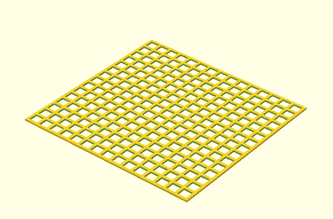
The end product should look something like this:
A simple alternative
This approach produces grids by intersecting rows of rods with columns of rods, similar to a fence. It is simpler but gives less control over the final dimensions.
window_num = 10;
window_size = 12;
strut_size = 8;
for (i = [0:window_num]) {
  rotate ([0, 0, 90])
  translate ([0, 0, (window_size + strut_size) * i])
  cube (size=[window_num * (window_size + strut_size), strut_size, strut_size]);
}

for (i = [0:window_num]) {
  rotate ([0, 270, 0])
  translate ([0, (window_size + strut_size) * i, 0])
  cube (size=[window_num * (window_size + strut_size), strut_size, strut_size]);
}