OpenSCAD is a popular tool to design 3D models using a powerful yet easy-to-learn scripting interface. Different to some other programs that allow you to shape a model more directly, this approach may have benefits in allowing you to specify measurements precisely, and allowing for easy reproducibility.
I’ve been playing around with it recently for some research related projects, and I’ve found that it is relatively easy on system resources, running well on my low end notebook computer. Today I’ll be outlining how to generate a basic modular grid/fenestrated surface using a few lines of code.
Setting things up
We’ll define three variables first up, making up the size of the surface that we will be later be poking windows in. This is completely up to you; for this example I’ll use the following:
x = 100;
y = 100;
z = 1;
Defining the windows
Next is to define the number of holes on each axis, and the relative size of the holes. Again you can change these variables as you like, but for now we’ll be using:
fen_x = 15; // fenestrations on x axis
fen_y = 15; // fenestrations on y axis
fen_size = 5; // size of fenestrations as a % of total axis size
Calculating some sizes
Using the two sets of variables that we defined earlier, we can work out some sizes - the window size and the amount of space we can allow for between windows and around edges:
// calculate fenestration size
fen_size_x = fen_size * x / 100;
fen_size_y = fen_size * y / 100;

// calculate space remaining and then divide by number of windows needed + 1 to get the desired size of the struts
strut_x = (x - fen_x * fen_size_x) / (fen_x + 1);
strut_y = (y - fen_y * fen_size_y) / (fen_y + 1);
Crunching the numbers
Finally, we can put it all together. In essence, what we’re doing is taking boxes away from our surface. So to do this, we can iterate over both the x and y axis the number of times we want the boxes to appear, distributing the next one over so that we get even spacing:
// take away windows from fenestrated surface
difference() {
cube(size=\[x, y, z\]); // fenestrated surface
for (i = \[0:fen_x - 1\]) {
translate(\[i * (fen_size_x + strut_x) + strut_x, 0, 0\])
for (i = \[0:fen_y - 1\]) {
translate(\[0, i * (fen_size_y + strut_y) + strut_x, -1\])
cube(\[fen_size_x, fen_size_y, z+2\]); // the fenestrations have to start a bit lower and be a bit taller, so that we don't get 0 sized objects
}
}
}
The end product should look something like this:
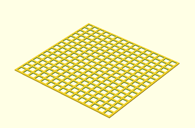
A simple alternative
This approach reliably produces grids by intersecting rows of rods with columns of rods, a bit like a fence. This contrasts with previous method which pokes holes in a solid object. It is nice and simple, so its easy to quickly pop in if thats all you need. One downside is that you won’t necessarily have as much control on how large the final object is. May not be a big problem, especially if you are planning to use the intersection() function to cut it further down to shape.
Variables
We’ll be using 3 variables for this method, the number of windows, the size of each window and the size of the struts. Again, the values associated with these variables is up to you.
window_num = 10; // number of windows
window_size = 12; // size of individual windows
strut_size = 8; // size of the struts
Telling the rods where to go
The next bit of code tells the program how to align each of the rods, based on the variables you’ve given it above:
for (i = \[0:window_num\]) {
rotate (\[0, 0, 90\])
translate (\[0, 0, (window_size + strut_size) * i\])
cube (size=\[window_num * (window_size + strut_size), strut_size, strut_size\]);
}

for (i = \[0:window_num\]) {
rotate (\[0, 270, 0\])
translate (\[0, (window_size + strut_size) * i, 0\])
cube (size=\[window_num * (window_size + strut_size), strut_size, strut_size\]);
}